Home - Genealogy - Other Gear
|
AUSTRALIAN WILLIAMSON AMPLIFIER SYSTEM
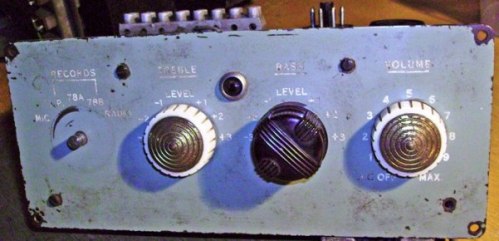
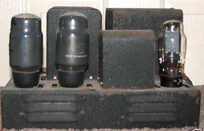
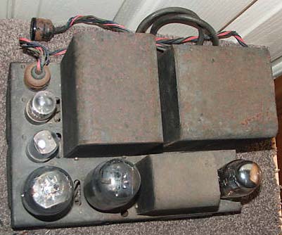
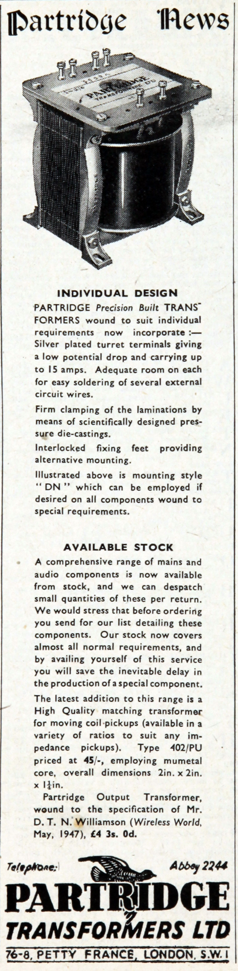
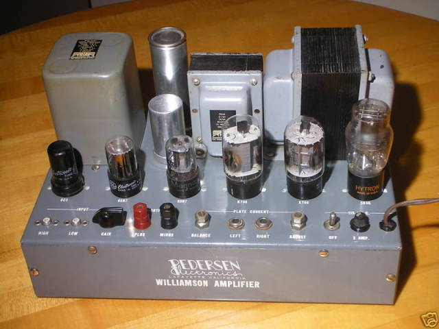
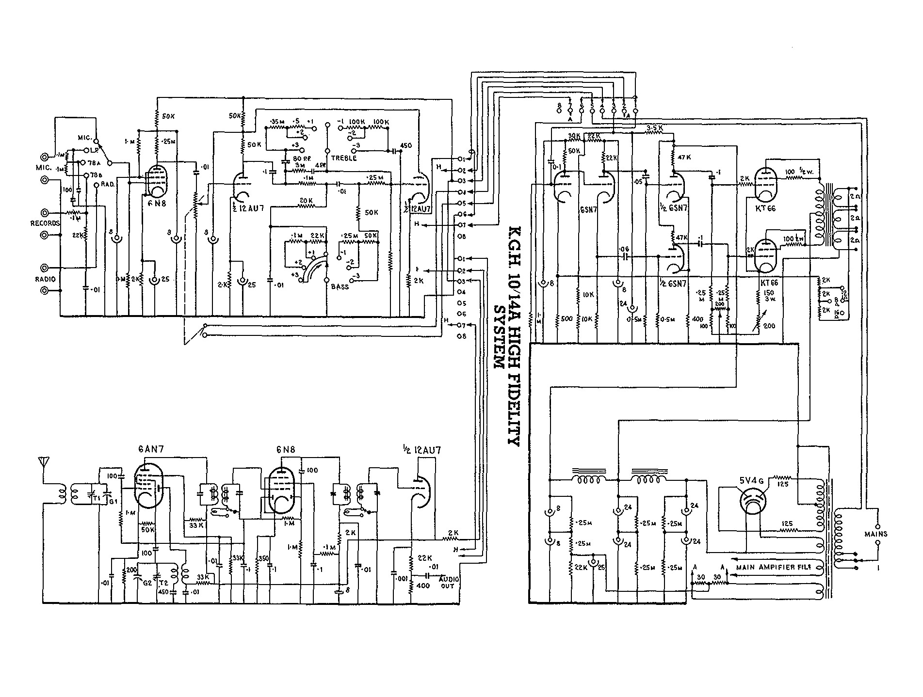
I am happy to share details on the restoration of seven Williamson amplifiers I am renovating. Four are Australian made: one is a kit from 1948 Radio & Hobbies; one is from a Model 10/14A radiogram circa 1954 made by K.G.H. from Sydney and has a control unit; one is possibly by AWA (using Red Line transformers and chokes); and one is an Audio Engineers with its control unit (perhaps circa 1953). Three are English made: one by Rogers circa 1951 (possibly a Model D); one by Goodsell GW18 (perhaps circa 1954); one by Miller Organs circa 1960 (probably in a Classic IV organ that came to Australia). Links and a brief summary are also provided to a compendium of Williamson amplifier articles. The Williamson amplifier abruptly garnered widespread interest with the technical community in England, Australia and USA in 1947-1949 through articles in the Wireless World magazine, and possibly was the most updated amplifier design of its time. It effectively spearheaded a significant boost in amplifier performance that coincided with speaker and recording improvements to meet a growing post-war appreciation and demand for hi-fi reproduction. In Britain, the hi-fi manufacturers Rogers, Goodsell, E.M.G. and Expert put Williamson amplifier designs at the top of their product range, and Pilot Radio, Radio Craftsmen, Sun Radio, Harvey Radio, Heathkit, Knight, and Pedersen made versions in USA, and Electrohome in Canada, with manufacturers like Grommes making more substantial changes to the circuit. Australia however didn't seem to have a widespread commercial uptake, although initial technical interest was high and a number of kit and part makers supported the amplifier. The following photos are of a commercially made Australian amplifier and preamp that is unbranded and from 1952-3, and made by K.G.H. as part of its Model 10/14A radiogram (3 valve radio, 2 valve preamp, 3 valve amp + rectifier valve). Likely advertised as an 8 valve radiogram with microgroove auto changer - any details appreciated ! It uses the 1949 'new' version of the Williamson circuit, with a few practical but subtle changes. The output transformer has three secondary windings, and three 2k resistors for feedback adjustment - see schematic link below for KGH. The control unit has the typical preamp layout of the time, with switched bass and treble settings, and the LP, 78A, and 78B compensation settings for the records of the time. |
 |
 |
 |
|
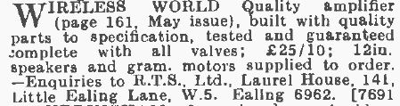
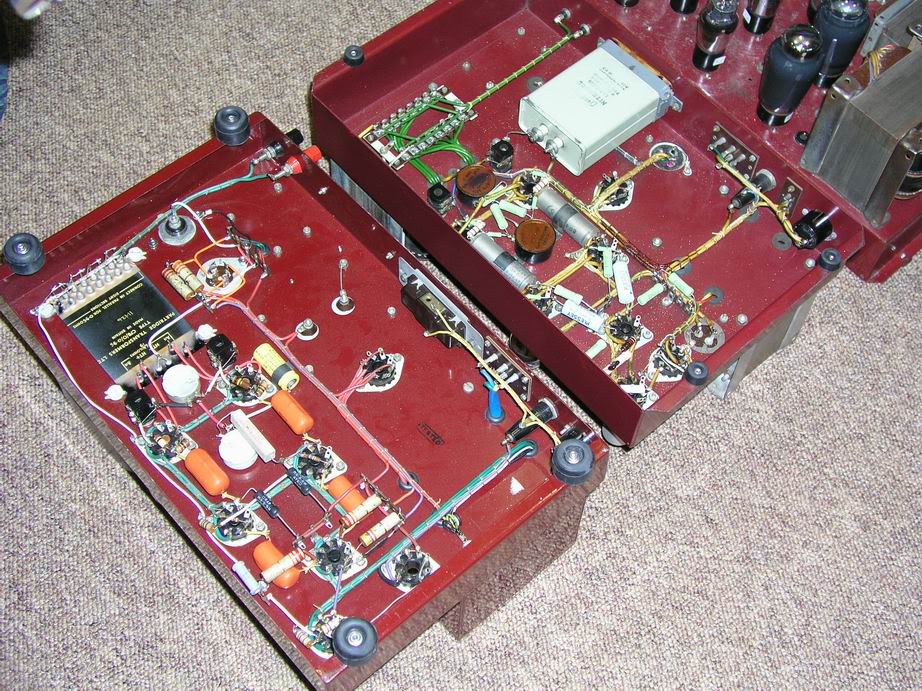
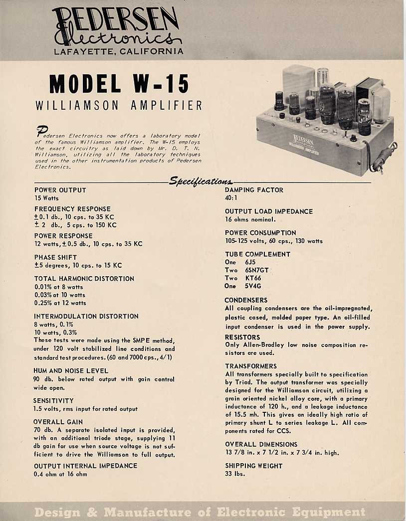
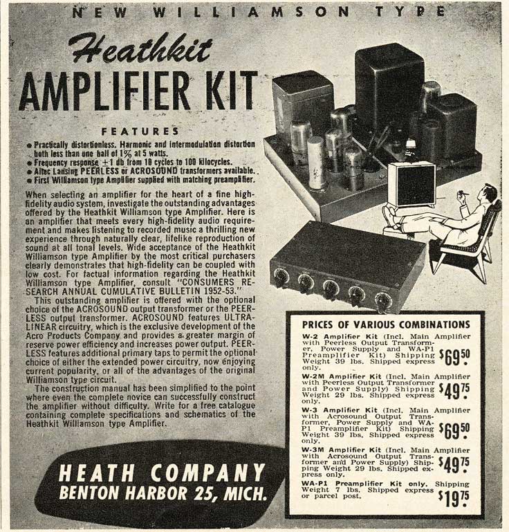
Williamson amplifier restoration information - specific to the Australian K.G.H. radiogram Model 10/14A. Williamson amplifier restoration information - specific to the Miller Organs English manufactured amplifier using the 1949 'new' version, but with screen-regulated 807 output valves, and a full set of Partridge transformers and chokes. Williamson amplifier restoration information - specific to the Australian Radio & Hobbies A515 amplifier project from 1948. Williamson amplifier restoration information - specific to the Australian Audio Engineers amplifier advertised from 1952. Following is a compendium of historical articles and links related to the Williamson amplifier. Douglas Self has scanned the original Wireless World April and May 1947 articles by Williamson. The first advert for commercial transformers for the Williamson articles appeared in July, and the first built amplifier was available from R.T.S. Ltd in August for 25 pd 10 sh. Partridge made an output transformer commercially available from September 1947 (WW advert), and Goodsell started selling a complete amplifier with Partridge transformers from October 1947. The Australasian Radio World monthly magazine reprinted the WW April and May 1947 articles in their August 1947 issue. The Williamson Amplifier - the Wireless World compendium of Williamson articles from April 1947 to May 1952. The 'new' version of the power amplifier, along with preamplifier articles and practical construction advise were in August to December 1949 issues. The 'new' version increased the driver stage anode loads from 39k to 47k and removed the 25k pot, and added a 4k7-200pF step filter across the anode load of the input stage. 1947 A515 article in Australia's Radiotronics No.128 - published just 6 months after the original Wireless World article - the amp results used 6SN7's and 807's, and a Goodmans transformer they just happened to have available. "Intermodulation Measurements on Radiotron Amplifier A515" - more results in following issue of Radiotronics No.130 (March 1948) that presumably used the new Ferguson OP25/15 (1948 advert links below and measurement article at end of page). And it's not surprising that Langford-Smith and Aston were quick to check out Williamson's design given the work Aston had been doing on A513 and A514 amplifier design at the time. A summary of Williamson related references from the Australasian Radio World magazine over the period August 1947 to October 1950. Includes links to comments about the high interest in the amplifier, various modifications, Red Line adverts, and a caution about how few operated perfectly. NZ Radio and Electronics article in Sept 1948 on using 807's in simpler circuitry to approach Williamson performance. For 1948 this is a good read on applying feedback and simplifying the power supply to achieve a practical amp when comparing to the Williamson benchmark. Reprint of the Radiotronics A515 article - in January 1948 Australia's Radio & Hobbies magazine. Ferguson Transformer advert for OP25 in February 1948. Ferguson Transformer advert for OP25 from Mar 1948. Triode-connected 807 Amplifier - Radio & Hobbies March 1948 article, headlined as the Amplifier to End Amplifiers. NZ Beacon Radio output transformer 48S06 adverts in NZ Radio and Electronics from July 1948. Partridge technical datasheets from WWFB/0 in Aug 1949 to CFB in 1951. Partridge information, including T/CFB UL. Gilson technical datasheet for WO.1796 output transformer. Woden technical datasheet for WOT.25 output transformer. Courtesy of John Howes, Howes Acoustics. Partridge 1965 price list, and connection info. Australian BRICO Radiogram schematic from 1948 - The Australian Official Radio Service Manual (AORSM) includes three radiogram schematics for models 5880 (1948), 5590 (1949) and 5500 (1950) made by BRICO in QLD. All schematics are the same, and show the 1947 Williamson circuit, but with the interesting inclusion of an additional 6SN7 between the first stage and PI stage. Novel 12W amplifier - Jan 1949 Radio-Electronics adaption of R&H article, but no mention of Williamson! The Swedish Popular Radio magazine had a 2-part article on the Williamson amplifier in May and June 1949 (p128-131, p162-162). Electrosound Model RW amplifier advert in July 1949. August 1949, Radio-Electronics - A High-Fidelity Tuner-Amplifier, Part 2, pp 38-40, by M. Harvey Gernsback. Follows on from their January snip of the R&H amp circuit, and integrates it with a tuner and preamp. A credit to Williamson is buried deep in the article. The feedback level is made switchable from 0 to 20dB, and a few paragraphs alert the user to potential instability for certain output transformer and speaker choices, and a need for appropriate test equipment if high levels of feedback are to be entertained. Part 1 (July) and Part 2 link. "Musician's Amplifier", Sarser & Sprinkle, Audio Engineering, November 1949. - linked from Dennis Grimwood's webpage discussing this slightly tweaked version of the Williamson circuit. The author's effectively introduced the Williamson amplifier to USA with this article. The only differences to Williamson's 'new' circuit were triode connected 807's, some changes to the powering circuitry, and a somewhat simplified bias current setup, although the input stage phase margin improvement RC network was not included (probably due to short time since the August WW had been available). At that time, the authors could only identify the Peerless S-265Q output transformer as being suitable for the task. Better scan here October 1949 Audio Fair & AES Convention - Peerless exhibit the Musician's Amplifier , from Electronics, Jan 1950. Suggestions for Amplifiers - Radio & Hobbies December 1949 article on combining a preamp with main Williamson amp. John Gjetting presented 7 articles on the Williamson amplifier in the Swedish Radio Ekko magazine from 1950. The first article in March 1950 is not yet available – the remaining articles were Jan 1951 (pp.14-15), May 1951 (pp.79-80), June 1951 (pp.90-91), July 1951 (pp.106-107), May 1952 (pp.82-84), and June 1952 (pp.97-99). "Williamson" type amplifier using 6A5's, by J.H.Beaumont, Audio Engineering, October 1950. A practical combination of preamplifier and amplifier with 12AX7 valves and 6A5 DHT output valves resulted in feedback level being dropped to 5dB, and coupling capacitor values dropped to provide stable operation, albeit with a lowered bandwidth. A wide range feedback amplifier, by R.M.Mitchell, Radio & Television News, October 1950. The article highlights the deficiency in commonly available test equipment (circa 1950) for measuring the low distortion and observing the fast rise-time squarewaves provided by the Williamson amplifier. Building the "Williamson" Amplifier, by H. Kereos, Radio & Television News, December 1950 article. Kereos puts forward the Acrosound TO-290 output transformer in a diy article. The only change from the WW new circuit is again the USA use of 807's like the Musicians Amplifier, but also the addition of an output stage cathode bypass capacitor to reduce distortion as the 807's approach class AB operation (and class A constant cathode voltage conditions start to degrade). An interview with David Hafler. in the Vacuum Tube Valley Issue 14, provides insight in to the early days of Acrosound and their Williamson related output transformers. Audio Feedback Design - Part 3, by G.F. Cooper - Radio Electronics, December 1950 article. The article details the Williamson circuit's low-frequency and high-frequency response performance, and the design considerations and trade-offs needed for achieving stable operation for the given level of feedback, and the bandwidth over which the feedback is effective at reducing distortion. Goodsell made the GW-12 and GW-18 amplifiers - product info and photos from ebay. Goodsell advertised a 'Williamson' amplifier from Dec 1949 in WW. Goodsell example of Williamson. A photo compilation of a Rodgers amplifier, and a photo of a clean Rodgers amp. UTC United Transformer Company 1951 catalog - description of their finest Output Transformers suitable for Williamson amp, including their W-10 and W-20 kit amplifiers with performance response. Audio Amplifier Dampening, R.M. Mitchell, Electronics, September 1951. The theory and measurement of amplifier output damping factor is presented, and the UTC-W20 Williamson based amplifier used for measurement. Stancor Transformers brochure, and here - for their Williamson amplifier module using the A-8054 OT. Commercial custom built "Williamson" Amplifier - AE-60. Featuring parallel KT66's and Acrosound's TO-330 output transformer, this amplifier provided up to 60W. (possibly circa 1952) High-Fidelty Fall 1951 magazine has numerous references and adverts for the Williamson amplifier design. Link. In November 1951 the dutch Radio Bulletin magazine presented an article on the Williamson to its readers. The initial paragraph translates as "It is certainly interesting for the RB reader who has no access to foreign journals to appreciate the field of modern quality amps around the world even before they are for sale. In recent years in particular a design has acquired great renown: the "Williamson". The first publication in "Wireless World" dates from April '47 and is the work of D. T. N. Williamson, which is connected to the Ferranti factories. The best proof of the extraordinary qualities of this design is probably the fact that in America there is a growing demand for the material produced by the English factories, according to the Williamson specification!" Audio Facts, PF Index and Technical Digest, Jan-Feb 1952. Discussion by R. Dunham on the popular use of the Williamson amplifier, and his construction of a Stancor kit. Heathkit introduced the W1-A1 amp in May 1952. W1 photo by Pete Basel. Charlie Kittleson wrote a summary article in 1995 on the Heathkit range in Vacuum Tube Valley Issue 2. Heathkit's W-2 first update in 1953 from the AudioKarma database and Dave Gillespie's excellent restoration thread. Harvey Radio advert from Feb 1952 AUDIO ENGINEERING for HR-15 kit amplifier. A High-Quality Audio Amplifier by E.S. Miller in Feb 1952 Radio and Television News. Design factors of Williamson circuit used in the Radio Craftsman Model 500 by their chief engineer. Radio Craftsmen introduced the 500 amp in late 1951. Of note is the change from first stage anode 47k load shunting by 200pF/4k7 shelf filter (17kHz corner), to a 2k7/560pF load to ground, and the addition of some phase lead by paralleling 68pF across the 4k7 feedback resistor (500kHz corner). Also, the main capacitor coupling corner frequencies were staggered from 6.3 and 7Hz in the Williamson, to 0.7 and 16Hz in the 500. To further improve noise performance, the valve heaters were 40VDC elevated to the output stage cathode level. "Audio Installation and Service" by K. Stewart, SERVICE, Nov 1952. "Installation & Sevice Instructions". General service information on the C500. Charlie Kittleson wrote a summary article in 2003 on the C500 amp and its upgrades in Vacuum Tube Valley Issue 19. Pilot Radio introduced Pilotone amplifiers (eg. AA-901) in 1952. Product brochure from 1952. Another product brochure from 1952. Pedersen Electronics had the W-15 amplifier. Product brochure. Photo from ebay. Electrohome had the W-15 amplifier. www.canuckaudiomart.com forum post. Ebay photos and circuit and manual. The Williamson design became a benchmark for discussing aspects of amplifier design such as Audio Impedance Measurement by J.A. Mitchell in April 1952, Radio Electronics, and The importance of balance in push-pull amplifiers by J. Marshall in July 1953, Radio Electronics, and High-Quality Circuits by J.K. Frieborn in Sept 1953, Radio Electronics. Front end control unit for Williamson Amplifier, A.J. Rose, June 1952, Radio and Television News. "Ultra-Linear Operation of the Williamson Amplifier" by Hafler & Keroes, Audio Engineering, June 1952. UL operation of the output stage was brought on to the 1950's public stage by Hafler & Kereos in Nov 1951. Dennis Grimwood provides an excellent historical and technical overview of UL, that sets the scene for its implementation in a Williamson design context at that time. Apart from the UL related changes, the authors also staggered the capacitor coupling corner frequencies for better low-frequency stability (7Hz reduced to 1.4Hz for first coupling), added some phase lead with the feedback resistor (150kHz corner), and bypassed the output stage cathode resistance for lower 3rd harmonic distortion. "Gilding the Lily", Sarser & Sprinkle, Audio Engineering, July 1952. - ultra-linear operation update to their Musicians Amplifier article from Nov 1949 - plus zinger response by Hafler & Keroes. DIY article based on Stancor kit of parts for Williamson amplifier Practical Williamson Amplifier by F.A. Gicca in July 1952, Radio Electronics. "The 'Williamson Type' Amplifier Brought Up to Date" by M. V. Kiebert - August 1952, Audio Engineering. An update of an update of an update - an important insight in to practical noise and distortion improvements based on parts selection and applying standard hum reduction technique. Hal Layer built his Williamson amp back in 1959 based on this article - great pictures. An Economy Audio Amplifier by G. Philactos in Nov 1952, Radio and Television News. This amp has effectively no similaritiy to the Williamson design, and appears to site "Williamson" only for its star appeal. The Maestro - a POWER Amplifier, by D.Sarser & M.Sprinkle in Nov 1952, Audio Engineering. Steroid version of the 'Musician's Amplifier' from Nov 1949, with 6146 output stage valves operating in beam tetrode mode with fixed bias and regulated screens, and delivering 90W. "Improving the Williamson Amplifier" by Hafler and Kereos, Radio & Television News, February 1953 . Similar article to their June 1952 article in the Audio Engineering magazine. UTC W-20 Williamson Amplifier Kit - Audio Engineering magazine 1953 technical report for parallel 1614 version. An extract from UTC 1953 catalog 530A with schematics of W-10 and W-20 kit amplifiers, including some photos of a W-10 amp. Laboratory Tests of some of the popular audio amplifiers, T.O. Dixon, April 29, 1953 - NRL Report 4136. A summary of frequency response tests made on hi-fi amplifiers available at the time, including a variety of Williamson style commercial amplifiers and output transformers made for Williamson style circuits (including Peerless S-265Q, Partridge WWFB and CFB). Radio and Television News magazine continued on from the Feb 1952 article by Hafler & Kereos with two more update articles: A Linear Power Amplifier by F. Brewer in April 1953 using a low cost output transformer with added interstage feedback, and The 'Linear Standard' Amplifier by J.Z. Knapp in May 1954 - Knapp was from UTC, and the proposed amplifier had little similarity to the Williamson circuit. Of interest was that some type of a Williamson amp was assessed for performance, with particular focus on how the out-of-band peaking from a lack of low and high frequency step networks could affect low frequency transient response (eg. from turntable rumble), and high frequency response from increasingly capacitive speaker impedance - however the article does not disclose the output transformer used for testing, so measured results may be quite uncharacteristic of the original Williamson performance. "Ultra-Linear Williamson-Circuit Amplifier" by W. Martin, SERVICE, June 1953. General introduction of the Brociner UL-1 amplifier. An interview with D.T.N. Williamson in New York by Ed Wallace in July 1953, High Fidelity. By this stage, Williamson's attention had turned to loudspeakers, and prototyping his Ferranti tonearm and pickup. Art and Science in Sound Reproduction, by F.H.Brittain, August 1953. Brittain worked for GEC in their acoustics research group, and had a recent 2-part WW article on a metal cone loudspeaker that is a main chaptor in the book. GEC/Osram obvioulsy bankrolled the book, which is dominated by Osram valves used in audio preamp, amp, tone and radio chapters in the book. Williamson had long left Osram, so although his amplifier and its aims are central to Brittain's amplifer chapters, Williamson is only recognised by a photo of his 30W prototype prepared for Osram back in 1945. Extended Class A Amplifier by L.B. Hust, Radio & Television News, Sept 1953. Modified Williamson amplifier with fixed bias and parallel 807 output stage with one in triode mode and the other tetrode mode for 50W rating. Dubious use of 1mH radio-frequency chokes in serious with load resistors in phase splitter and driver stages. Multiple-Feedback Audio Amplifier, J.M. Diamond, Electronics, November 1953. Although focussing on using a tetrode mode 807 in the Williamson circuit's output stage, along with local anode-grid feedback, the circuit presented has little other comparison. "The Williamson Amplifier - A Modified Design" by R. Dunham, PF Index and Technical Digest, February 1954. General comment on Williamson status since Feb 1952 discussion, and construction of the UL version of a Stancor kit. "Audio Facts - Testing a high quality audio amplifier" also by R. Dunham, PF Reporter, Oct 1956. General comments on testing using the same Stancor Kit as an example, and including I.M. distortion results. "An analysis of the Williamson Amplifier" by M. Vino, SERVICE, April 1954. General introduction of operational stages for servicing. The 1954 successor to Sweden's Popular Radio magazine was Radio och Television, which ran a series of Williamson amplifier construction articles from April 1954 (pp.28-31), May (pp.24-26), June (pp.18-24). Letters p38/May, p50/Oct, p43/Dec. System Design Factors for Audio Amplifiers, Kiebert & Mallory - IRE National Convention, 1954. Assessment of further improvements to Williamson design. Stancor Williamson Amplifier brochures - 1953 and 1954 brochures, which indicate over 5,000 of the standard (non-UL) Stancor Williamson amplifiers had been sold by March 1953. Stancor Ultra-linear Williamson High Fidelity Amplifier using Stancor Ultra-linear Transformer A-8072 - 1954 brochure, which indicates over 7,000 of the standard (non-UL) Stancor Williamson amplifiers had been sold by April 1954. FREED Transformer Bulletin 5402 using FREED transformers and chokes for Williamson amplifier including the KA-10 output transformer. Sept 1954, Audio - Versatile control unit for the Williamson, pp 19-21,78, by Charles R. Miller. A series connection of the preamp valve heaters are powered from the Williamson output stage common cathode voltage of 40VDC, and neons are used to avoid voltage limit problems if the heater connection goes open circuit. Link. Gold plated H-4111 Output Transformer by Gramer Halldorson for Williamson amplifier - 1955 catalogue. HMV initially used a Williamson amplifier module in their flagship model 3000 range of radiograms introduced from 1955. In 1956, a standalone amplifier model 3051 along with a preamplifier model 3050 were coupled with 5 speakers as a 3052. A few common circuit changes were introduced to the amplifier, including the step network, increased input/splitter decoupling capacitor values, and staggered coupling cap values, along with using the 12AU7. Mostly courtesy of John Howes. HMV/EMI in Australia introduced the Model 91-45 rediogram in 1955, which included a Williamson type main amplifier with quite a few circuit based differences including a 12AX7 for the input and PI stages, and separate cathode biasing for the KT66's. Also, K.G.H. in Sydney made a Model 10/14A radiogram for commercial outlet sales, which included a Williamson main amplifier - the schematic is almost an exact copy of the original. A 60W 'Ultra-linear' Amplifier, by David Hafler - Radio & Television News, Feb 1955. Hafler presents Acro TO-330 with parallel KT66 valves in UL mode to achieve 60W output. Hafler & Kereos' previous 1952 circuit tweaks were used, along with tuned humdinger DC voltage elevation of heaters, and contingency 250pF shunting one half-primary of output transformer for problem loading. Circuit Design Factors for Audio Amplifiers, M.V. Kiebert, Electronics, April 1955. Implementation of a cathode follower driver stage for AB2 operation of output stage using a 'kicker' supply. Includes Kiebert's recent efforts to improve Williamson circuit subsequent to his 1952 article. “Effect of the Cathode Capacitor on P-P Output Stage”, by R.M. Mitchell, p.21, AUDIO, Nov 1955. UTC W-10 Williamson amplifier used to measure THD and IM with/without a bypass capacitor for KT66, 5881, and 1614 output valves, and for varying degrees of circuit unbalance. In general, results showed that THD could rise or fall, depending on the valve. CCIF IM results in general showed a slight improvement at higher output power levels with the bypass capacitor. Preamplifiers for use with Williamson Amplifiers, by F. Langford-Smith - Radiotronics, June 1955. A short article describing how preamplifier design may influence stability of a connected Williamson amplifier - in particular when using a common power supply. This edition of Radiotronics also includes a good article on square-wave testing of hi-fi amplifiers. Adapting the "Ultra-Linear" Williamson to 6550 Operation, by Keroes - Radio & Television News, Nov 1955. Kereos presents Acro's updated higher powered version using fixed-bias 6550 valves in UL mode. Hafler & Kereos' previous 1952 circuit tweaks were used, along with 470k shunting of coupling capacitors to compensate low-frequency phase shift, 220 ohm cathode degeneration on the driver triodes, and tuned humdinger DC voltage elevation of heaters. ACRO put out an updated catalog with circuits and technical discussion to support this latest UL amp using 6550, along with a collation of other Williamson variants. A 100-Watt Power Amplifier, by A.K. Olson - Radio & Television News, Nov 1955. A fixed bias 6550 beam pentode mode amp design, but using output transformer tertiary windings for cathode feedback. Quite a few other circuit changes are immplemented, compared to the Williamson circuit, resulting in reduced high frequency bandwidth. High-power Williamson amplifier for Hi-Fi, by David Hafler - Radio-Electronics magazine Dec 1955 technical article. Fixed bias 6550 valves in UL mode achieved 50W output. Hafler & Kereos' previous 1952 circuit tweaks were used, along with 1Meg shunting of coupling capacitors to compensate low-frequency phase shift, high frequency 100pF feedback from driver stage to first-stage feedback node, and tuned humdinger DC voltage elevation of heaters. Heathkit W5-M Amplifier Kit - detailed 1955 kit assembly and operation booklet, but no recognition of Williamson. Includes various performance plots for power, distortion and frequency response. Same vintage but better low frequency response than W-4M. Heathkit "Williamson Type" W3-M Amplifier Kit - detailed 1955 kit assembly and operation booklet. Heathkit "Williamson Type" W3-AM Amplifier Kit - detailed 1958 kit assembly and operation booklet. Heathkit "Williamson Type" W4-AM Amplifier Kit - detailed kit assembly and operation booklet. Heathkit Williamson amplifier advert, and installation article for preamp and amp. The Heathkit 70W W-6M Amplifier from 1957 had many changes from the original Williamson circuit - including variable current feedback to modify the damping factor, an additional cathode follower driver stage that integrates fixed biasing for the 6550 UL output stage, and ss rectifiers. The operating manual includes technical performance details for overload recovery. Phil Nelson has a restoration webpage on the amp. Dynaco reprint of the Audiocraft Jan 1956 "Modernize your Williamson" by David Hafler. (Scan appears to be missing a page). Hafler describes modifications including using EL34/6CA7 with a Dynaco A-430 output transformer, along with his 1955 mods, but also identifies the risk of adding the 1 Meg bypass of coupling caps, and the performance change with the high-frequency 100pF feedback from driver to input stage. The other major change is removing the cathode bias resistors, and including a fixed bias circuit. Audiocraft article. "High Fidelity Power Amplifiers" by Marshall - Radio-Electronics, May 1956. A summary of design evolution, including original Williamson, progressing through the use of UL, and in to cathode loading designs. "A 20-Watt Amplifier System" - review of the EICO HF20 ultra-linear version of the Williamson amplifier - Radio and Television News, July 1956. The HF20 uses 6L6GB valves, with bypassed common cathode used to elevate the heaters. The coupling cap corner frequencies are staggered, the power supply decoupling caps for input and PI stages are increased, a shelf filter is added to inpuit stage anode load, and feedback resistor is paralleled with phase correction cap. "The Care and Treatment of Feedback Audio Amplifiers" by W.B. Bernard - Audio, Jan 1957. Discusses feedback, and in particular related to the Williamson amplifier. Provides practical oscilloscope response examples of before/after changes for stability improvement. Highlights the general lack of access to test equipment, and the poor performance that some may be enduring as a result. "High fidelity circuit design" by N.H. Crowhurst & G.F. Cooper - 2nd Ed, April 1957. Includes an assessment of Williamson circuit in the 'design and analysis' chapter - no measured results, only estimations and based mainly on Cooper's 1950 article in Radio Electronics. "Distortion in audio phase inverter and driver systems" by W.B. Bernard - IRE Convention Record, Mar 1958. Discusses I.M. distortion differences between 6SN7 and 12AU7 values used in the Williamson amplifier phase inverter and driver stages. Provides insight in to measurement issues, and describes a possible improved circuit structure. Details on the Type 90 amplifier used in Allen Organ Co's Gyrophonic Projector from mid 1958. 90W amplifier with fixed bias KT88 in pentode mode. Uncertain origin as a Webster amplifier made for Allen Organs, and then brought in-house for manufacture. Beacon Radio 1958 catalogue from NZ, including transformers and chokes for Williamson amplifier. Improving the Williamson Amplifier by T. Wright - Electronics World, June 1961 article. Wright revises the operating bias points of the input, PI and driver stages to improve the linearity of each stage to achieve lower IM distortion levels. Wright also identifies where increasing the bypass capacitance of particular stages can improve transient response. Others have since followed up on Talbot's advice, such as by Dennis Boyle. The Radford MA15 Mk2 amplifier design was described in detail in HiFi News 1962 in 4 parts by Bailey and Radford. Design is based on the Mullard 20W amp from 1955, and the article makes comment on the Williamson and provides some good insight in to extending high frequency performance. The Williamson output transformer was described as having "immense proportions" to achieve low phase shift at low frequencies, and the high frequency shunt resonance was too low "to provide a gradual roll-off in the forward gain" before OT resonance interaction. And although core and winding advances by 1962 allowed a more economic transformer to be made, the MA15 Mk2 still required a special and custom output transformer with tuned feedback networks in order to achieve the stability requirements, especially as negative feedback was increased to 27dB. . "Stereo amplifier with acoustic unit" by Y. Romanyuk - Radio Magazine, October 1965, pp.47-49. A soviet magazine article with no reference to Williamson for their bass centre channel amplifier using a 6C4C fixed bias output stage. "Transistor driver for Williamson valve amplifier" by S. Berglund - WW, April 1976. Replacing all stages before the output stage with ss circuitry. Indicates 'obvious improvements' are made, but no benchmark comparison as KT88's are used. Bert van der Kerk's webpage - detailed guide to the circuit design, output transformer construction, and amp setup procedure, with some history and great photos. Keith Snook's webpage - detailed schematic guides. Great photos of amplifier parts and magazine extracts. Dennis Grimwood's informative insight on the amplifier design. The Williamson Amplifier - Electronics Australia July 1990 article by Peter Lankshear, pp.150-153. The Williamson Amplifier of 1947, by P.R. Stinson - an amazingly in-depth and well compiled 1991 biographical account of the background, development and fortunes of the Williamson design - now updated to September 2020. Peter was in correspondence with Williamson on biographical and technical details, and has provided this revised document with super photos of equipment. The Evolution of Audio Amplifier Design, Part 1 - Electronics in Action Feb 1994 article by John Linsley-Hood. John built a Williamson, and made the output transformer using a kit. The Williamson Amplifier Revisited - Elektor Electronics Extra Sept 1997 p.12-16 article by B.v.d. Kerk. Summary and notes of Williamson amplifier. The Williamson Amplifier - a Vintage HiFi review by John Howes, Ken Kessler, & Paul Miller in www.hifinews.co.uk in Jan. 2010. Courtesy of John Howes, Howes Acoustics. The Scotsman newspaper article on D.T.N. Williamson from 19 Aug 2011, with very interesting historical comments by Professor Joe McGeough of Edinburgh University’s School of Engineering. Morgan Jones' 2012 book Valve Amplifiers , 4th.Ed, has a short technical summary on 'The Williamson' in the Classic Power Amplifiers section - 2012, pp470-472. P.Paolo Ferrari has written a 460 page book in Italian on the history of D.T.N. Williamson, titled 1947 L’anno di D.T.N. Williamson, and published 2013 by Sandit. Paolo's webpage lists all his articles, has fantastic info on LEAK, and much more! How the Williamson amplifier changed the sound of music - Prof Joe McGeough - 25 Jan 2017. A presentation to Lothians Radio Society, including MS Powerpoint slides. Williamson design info - a collation of design details I put together for the 'new' Williamson amp circuit, along with a listing of changes known to have been made. An article on output transformer measurements for the Williamson amp. Williamson went on to design the Ferranti Ribbon pickup and be a key contributor to the original QUAD electrostatic speaker, and then moved to other areas - the sum of scientific excellence recognized by his election as a Fellow of the Royal Society in 1968, and an honarary doctor of science degree in 1971. |
|
Update: 7 May 2026
Email tim for comments/details Back to Projects Page |